| Material | Matrix | Male part | ||||||
|---|---|---|---|---|---|---|---|---|
| thickness | hardness | angle β | r1 | s | No. | angle α | r | No. |
| 1.05 | H2 | 65° | 1 | 6 | E5 | 45° | 1.00 | S3 |
| 1.05 | H3 | 75° | 1 | 10 | E6 | 45° | 1.00 | S3 |
| 1.42 | H2 | 75° | 1 | 10 | E7 | 45° | 1.00 | S3 |
| 1.42 | H3 | 110° | 1 | 10 | E8 | 45° | 1.00 | S3 |
| 2.0 | H2 | 110° | 1 | 15 | E9 | 50° | 1.50 | S4 |
*not suitable for creasing rules.
| Cuting rules | ||
|---|---|---|
| height | H | ±0.06 mm |
| Creasing Rules | ||
| Standard | H | +0 / -0.04 mm |
| Laser Crease | H | ±0.04 mm |
| Perforating Rules | ||
| height | H | ±0.06 mm |
| thickness S | tolerance |
|---|---|
| 1,05 mm | ±0,020 mm |
| 1,42 mm | ±0,025 mm |
| 2,00 mm | ±0,030 mm |
| 2,84 mm | ±0,030 mm |
| measured across the body. The maximum
tolerance results from height H according to the following formula:
z.B. for height 23,8 mm : |
 |
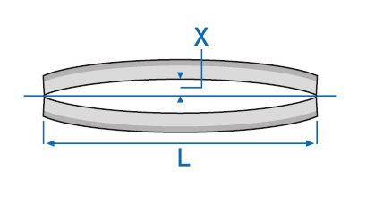
| straightness of the cutting edge or
the back of 1 meter length: |
||
|---|---|---|
| L = 1.000 mm | X max. | 1.2 mm |
| for lengths, back not notched | ||
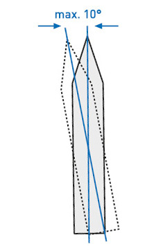
| admissible torsion on 1 m length: max. 10° for any height |
 |
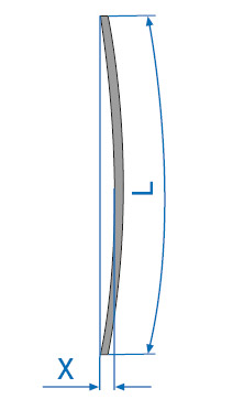
| meter lengths only:
length = L = 1.000 mm |
 |
|
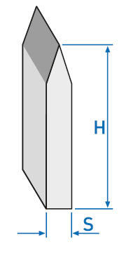
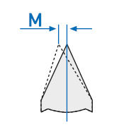
for centre bevel and long centre bevel:
|
 |
specific steel weight x height x thickness = weight per meter
i.e. 7.85 x 25.40 x 1.42 = 283 g/m
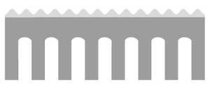
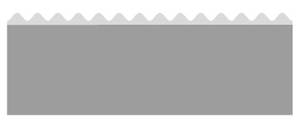 straight, not notched |
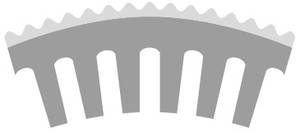
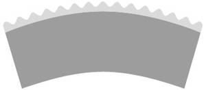 curved, not notched |
 straight and notched |
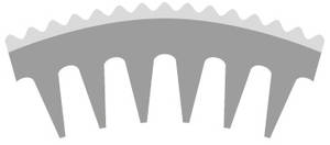
 curved and notched |
|
|
 curved, conical notching |
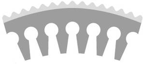
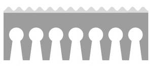 straight, keyhole notching |
 curved, keyhole notching |