Hardness’s for TopDurFlex edge hardened rules, hardening depth: min. 0.15 mm
| Hardness of cutting edge: | |
|---|---|
| 580 HV ± 20 HV (approx. 54 ± 2 HRc) | = standard |
| 700 HV ± 20 HV (approx. 60 ± 2 HRcv) | = alternatively |
| 800 HV ± 20 HV (approx. 66 ± 2 HRc) |
= alternatively |
Hardness according to customers‘ requirements: hardness indication
± 20 HV (± 2 HRc)max. hardening depth 0.3 mm. TopDurFlex cutting
rules are mainly produced from H2 or H3X steel.

| Body hardness’s for all rules: |
|---|
| H2 330 - 400HV ± 15 HV (ca. 32 - 41 HRc) |
| H2 for creasing rules 375 ± 15 HV (approx. 36-40 HRc) |
| H3x 405 ± 15 HV (approx. 40-43 HRc) |
| H3 435 ± 15 HV (approx. 43-46 HRc) |
| H4 520 ± 15 HV (approx. 49-52 HRc) |
| H5 605 ± 20 HV (approx. 54-57 HRc) |
| Material | Matrix | Male part | ||||||
|---|---|---|---|---|---|---|---|---|
| thickness | hardness | angle β | r1 | s | No. | angle α | r | No. |
| 0.71 | H2 TDF | 130° | 1 | 6 | E1 | 40° | 0.50 | S1 |
| 0.71 | H3x | 120° | 1 | 6 | E2 | 40° | 0.50 | S1 |
| 1.05 | H2 TDF | 120° | 1 | 6 | E2 | 40° | 0.50 | S1 |
| 1.05 | H3x | 110° | 1 | 10 | E3 | 40° | 0.75 | S2 |
| 1.42 | H2 TDF | 110° | 1 | 10 | E3 | 40° | 0.75 | S2 |
| 1.42 | H3x | 80° | 1 | 10 | E4 | 40° | 0.75 | S2 |
*not suitable for creasing rules.
| Thickness S | Tolerance |
|---|---|
| 0,40 mm | ±0,015 mm |
| 0,45 mm | ±0,015 mm |
| 0,50 mm | ±0,015 mm |
| 0,71 mm | ±0,015 mm |
| 1,05 mm | ±0,020 mm |
| 1,42 mm | ±0,025 mm |
| 2,00 mm | ±0,030 mm |
| 2,84 mm | ±0,030 mm |
| Cutting rules | ||
|---|---|---|
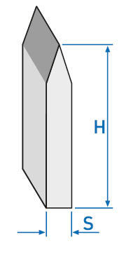
| height 8,00 - 12,00mm | H | +0,005 / -0,015 mm |
| height 23,80mm | H | ±0,02 mm |
| height 30,00 - 50,00mm | H | +0,01 / -0,04 mm |
| height 50,00 - 100,00mm | H | +0,02 / -0,06 mm |
| TDF Special 60 W any height | H | +0,005 / -0,015 mm |
| Wavy edge rules | H | +0,02 / -0,05 mm |
| Special Rules | H | +0,02 / -0,05 mm |
| Creasing Rules | ||
| Standard | H | +0 / -0,04 mm |
| Laser Crease | H | ±0,04 mm |
| Perforation Rules | ||
| Standard | H | +0 / -0,04 mm |
| Stripping Rules | H | +0,5mm / -0,2 mm |
| Stripping with Perf/ Speed Stripping |
H | ±0,5 mm |
| Waved Esopick / Stripping / Stripping with Perf |
H | ±0,5 mm |
| Spacing Rules | H | ±0,5 mm |
| Plane Steel | H | ±0,02 mm |
| measured across the body. The maximum tolerance results from height H according to the following formula:
z.B. for height 23,8 mm : |
 |
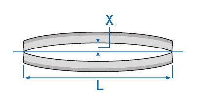
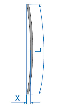
| straightness of the cutting edge or the back of 1 meter length: | ||
|---|---|---|
| L = 1.000 mm | X max. | 0,5 mm |
| L bis 500 mm | X max. | 0,3 mm |
| admissible torsion on 1 m length: max. 10° for any height |
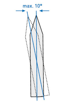 |
| meter lengths only:
length = L = 1.000 mm |
 |
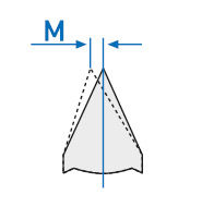
| for centre bevel and long centre bevel:
|
 |
| Thickness Height up to 25 mm |
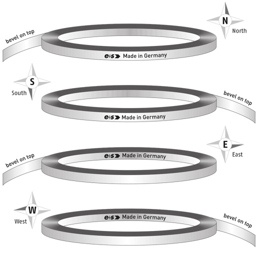
lengths | Coils inner diam. = 360 mm outside diam. = 470 mm |
|---|---|---|
| 0.40 mm / 1 pt (up to 12.0 mm height) |
100 m | 180 m |
| 0.45 mm (up to 12.0 mm height) |
100 m | 160 m |
| 0.50 mm / 1.5 pt (bis 24.0 mm height) |
100 m | 140 m |
| 0.68 / 0.75 / 0.82 mm | 100 m | 100 m |
| 0.71 mm / 2 pt | 100 m | 100 m |
| 1.05 mm / 3 pt | 75 m | 75 m |
| 1.42 mm / 4 pt | 50 m | 50 m |
| 2.00 mm / 6 pt | 40 m | 40 m |
| 2.84 mm / 8 pt | 25 m | 25 m |
other packaging units upon request
Specific steel weight x height x thickness = weight per meter
i.e. 7.85 x 23.80 x 0.71 = 132 g/m
 1.) shaved steel rule |
 2.) TopDurFlex edge hardened shaved steel rule |
 3.) ground steel rule |
 4.) edge-hardened ground steel rule |
 5.) micro-ground steel rule |
 6.) mirror-polished steel rule |
 7.) TIN-coated steel rule |
 8.) anti-adhesive steel rule |
 9.) stainless steel and brass rule |
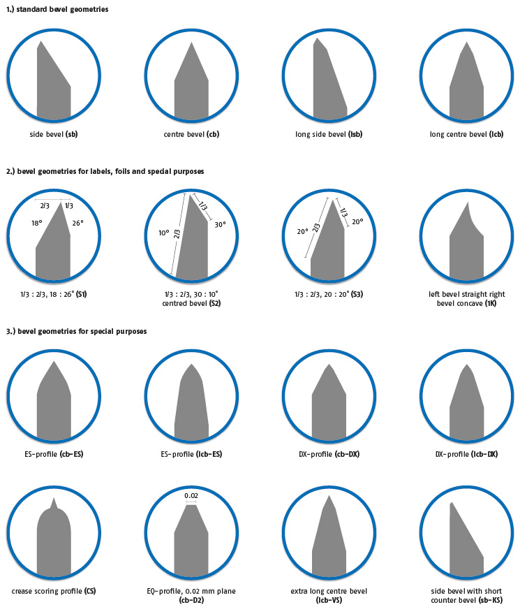
Further bevel geometries on request. Standard angle for centre and long centre bevels is 54°. Other often used angles are 30° and 42° angle.